Every electrical wire in your plant or office, whether it’s in a motor, generator, cable, switch or transformer is carefully covered with some form of electrical insulation.
The wire itself is usually copper or aluminium, which is known to be a good conductor of the electric current that powers your equipment.
The insulation must be just the opposite from a conductor, it should resist current and keep the current in its path along the conductor.
The purpose of insulation around a conductor is much like that of a pipe carrying water, and ohm’s law of electricity can be more easily understood by a comparison with water flow.
In Fig. 1 we show this comparison. pressure on water from a pump causes flow along the pipe (Fig. 1a). If the pipe were to spring a leak, you’d waste water and lose some water pressure.
With electricity, voltage is like the pump pressure, causing electricity to flow along the copper wire (Fig. 1b). As in a water pipe, there is some resistance to flow, but it is much less along the wire than it is through the insulation.

What is “good” insulation? “Good” means a relatively high resistance to current A suitable way of measuring resistance can tell you how “good” or “bad” the insulation is. When your plant electrical system and equipment are new, the electrical insulation should be “good”. Furthermore, manufacturers of wire, cable, motors, and so on have continually improved their insulations for services in industry.
Nevertheless, even today, insulation is subject to many effects which can cause it to fail – mechanical damage, vibration, excessive heat or cold, dirt, oil, corrosive vapours, moisture from processes, or just the elevated humidity on a muggy day.
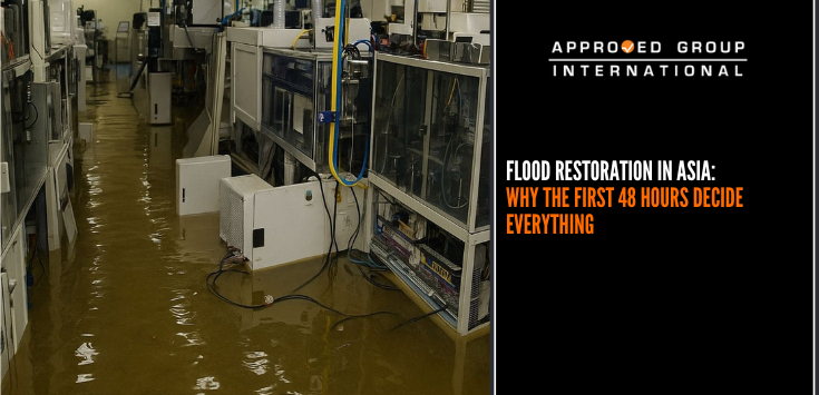
In various degrees, these enemies of insulation are at work as time goes on combined with the electrical stresses that exist. As pin holes or cracks develop, moisture and foreign matter penetrate the surfaces of the insulation, providing a low resistance path for leakage current. Sometimes the drop in insulation resistance is sudden, as when equipment is flooded. If there are no checks, may not only be dangerous to touch when voltage is applied, but also be subject to burn out. What was once a good insulation, has now become a partial conductor.

A basic megohmmeter hook-up schematic is shown in Fig. 1 (above). The megohmmeter is similar to a multimeter, when the latter is in its ohmmeter function. There are differences, however. First, the megohmmeter’s output is much higher than that of a multimeter. Voltages of 100, 250, 500, 1,000, 2500, 5,000, and even 10,000 are used (Table 1 below). The most common voltages are 500V and 1,000V. Higher voltages are used to stress an insulation to a greater degree and thus obtain more accurate results.
| Equipment AC Rating | DC Test Voltage |
| Up to 100V | 100V and 250V |
| 440V to 550V | 500V and 1,000V |
| 2,400V | 1,000V to 2,000V and higher |
| 4,160V and above | 1,000V to 5,000V or higher |
The most damaged coils were found to be turn-14 and turn-15, where severe inward deformation and damage were observed. A punctured hole was also observed on turn-14. Second, the range of a megohmmeter is in megohms, as its name implies, instead of ohms as in a multimeter. Third, a megohmmeter has a relatively high internal resistance, making the instrument less hazardous to use in spite of the higher voltages. Figs. 2, 3, and 4 show connections for testing three common types of equipment.


