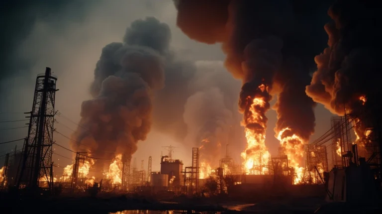
At approximately 2100 hours, the Operator first noticed sparks from an electrical panel adjacent to Extrusion Machine No. 6 in the Production Area. It then ignited into a fire and propagated upwards.
The fire-affected premises is utilised for the production and storage of plastic products including polypropylene (hereinafter referred to as PP) sacks and polyethylene (hereinafter referred to as PE) bags. The Production Area is enclosed within cement-rendered brick walls and topped with corrugated Galvanised Iron (hereinafter referred to as GI) roof sheets. There is a mezzanine floor constructed in the middle of Production Area (hereinafter designated as Middle Section). The floor of the ground floor is made of concrete, while the mezzanine floor is layered with metal panels. Production Area houses eight (8) extrusion machines and six (6) crushing machines.
Extrusion Machine No. 1 until No. 7 are arranged in line along the West Section, whereas Extrusion Machine No. 8 is placed at the East Section, near to the south wall (refer to Photograph 1).

The fire was fuelled by the plastic materials located within Production Area, which include the Finished Goods, Work-In-Progress, pure PE pellets, and scrap materials. Paperboard packaging materials, wood and plastic pallets, and containers contributed to the fire sustenance. The spread of fire was assisted by the electrical cables routed throughout Production Area, as the insulation burnt and consumed by the fire. Other fuel loads are plastic made electrical components within the extrusion and crushing machines, as well as the paint layers on the machines and construction elements.

Based on the fire damage interpretation, it was found that the fire had originated from within the electrical panel adjacent to Extrusion Machine No. 6. As the fire initiated from within electrical panel, the internal electrical components and insulation of the electrical reticulation were first consumed by the fire. The heated smoke plume, as well as fire spread upwards and outwards from the electrical panel. The fire spread through the insulation of the electrical reticulation above the electrical panel, subsequently igniting the stocks on the mezzanine floor as well as causing a drop-down spread of fire to the combustible materials on the ground floor. The availability of fuel load below the mezzanine floor within the Middle Section caused an intense fire, rendering the entire floor to collapse to the ground. The lack of adjacent fuel load on the floor of the East Section prevented a fire spread via direct flame impingement, however, the accumulation of hot smoke at the pitch of the roof causes severe oxidation and weakening of the structure. The Washing Area was affected mainly by the heat and smoke that penetrated through the East Entrance of Production Area. The subsequent electrical failure as a result of the fire caused the initiation of fire within another electrical panel nearby which spread upstream to the electrical room. The fire was initiated due to a high resistance heating which occurred at the terminal connection/contact points of circuit breaker(s) inside electrical panel located adjacent to Extrusion Machine No. 6 within Production Area.

- It is the Team’s recommendation that thermal scanning should be conducted periodically using Infrared (IR) Thermography devices to detect the presence of hot spot(s) radiated from the electrical reticulation and electrical appliances, particularly when the age of the electrical system is more than ten (10) years.


